I love it! especially the setting it on fire part
| gemellocattivo.com http://gemellocattivo.com/forum/ |
|
| Casting Marks Engine Parts http://gemellocattivo.com/forum/viewtopic.php?f=12&t=21 |
Page 5 of 7 |
| Author: | a1exander [ Tue Feb 10, 2015 12:25 am ] |
| Post subject: | Re: Casting Marks Engine Parts |
For me this was a brilliant post. Epic work |
|
| Author: | mk e [ Tue Feb 10, 2015 11:50 am ] |
| Post subject: | Re: Casting Marks Engine Parts |
I love it! especially the setting it on fire part |
|
| Author: | Brian.G [ Tue Feb 10, 2015 12:10 pm ] |
| Post subject: | Re: Casting Marks Engine Parts |
You'll be glad to hear I got my phone camera sorted - the lens cover was all scratched so gone are the milky shots. Brian, |
|
| Author: | Brian.G [ Wed Feb 11, 2015 3:50 pm ] |
| Post subject: | Re: Casting Marks Engine Parts |
Ok, so got these poured, With the camera in better form shots are better. Installation of filter in the filling sprue - this keeps out any dross or foreign items present in melt, 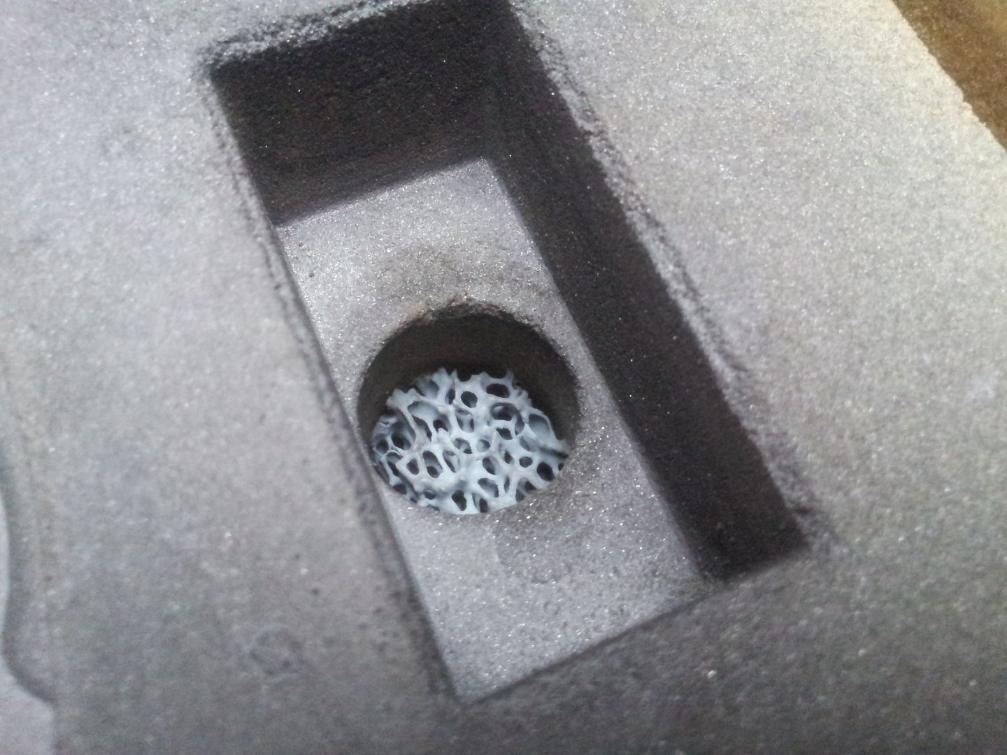 The moulds with the cavities above the parting line got drilled for vent holes, because the moulds have been coated with a light wash they become air tight, so, air has to be vented because alloy has not the power under gravity pour to displace the air,  Mould detail, 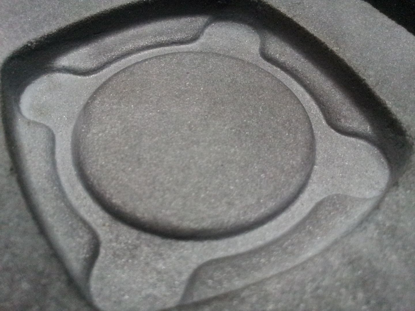 Glue is applied to lower mould and the top one placed on, 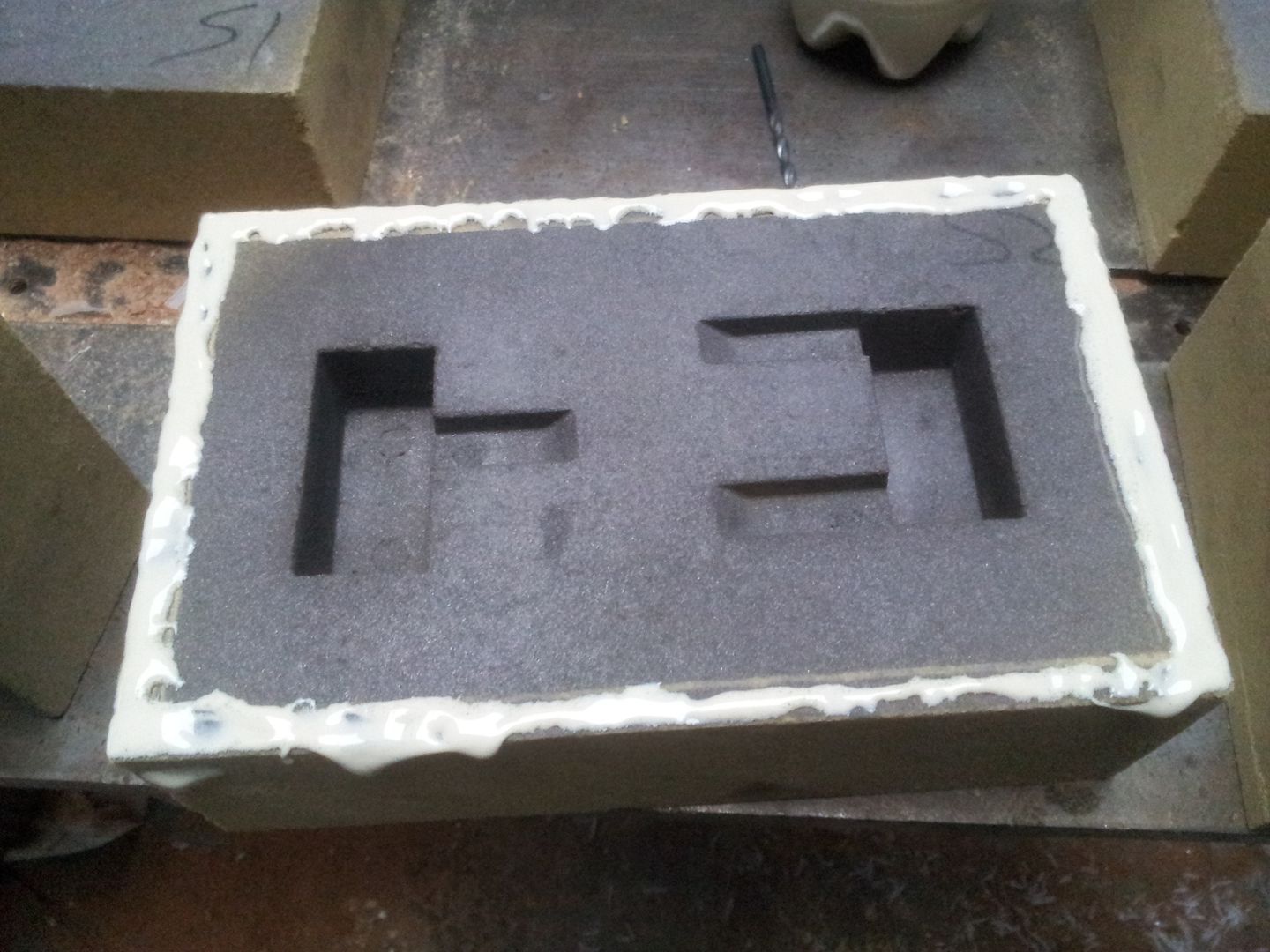 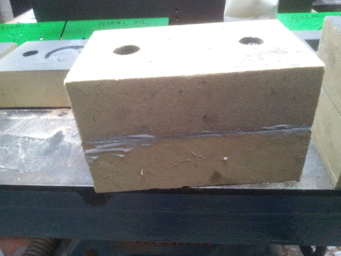 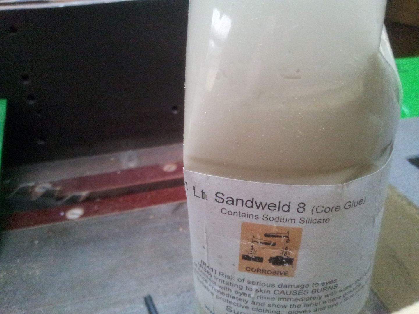 To make the mould form for the spigot that causes the hollow in rear of three bolt flange a piece of pipe is used of correct size with a slit in wall to allow sand core removal, 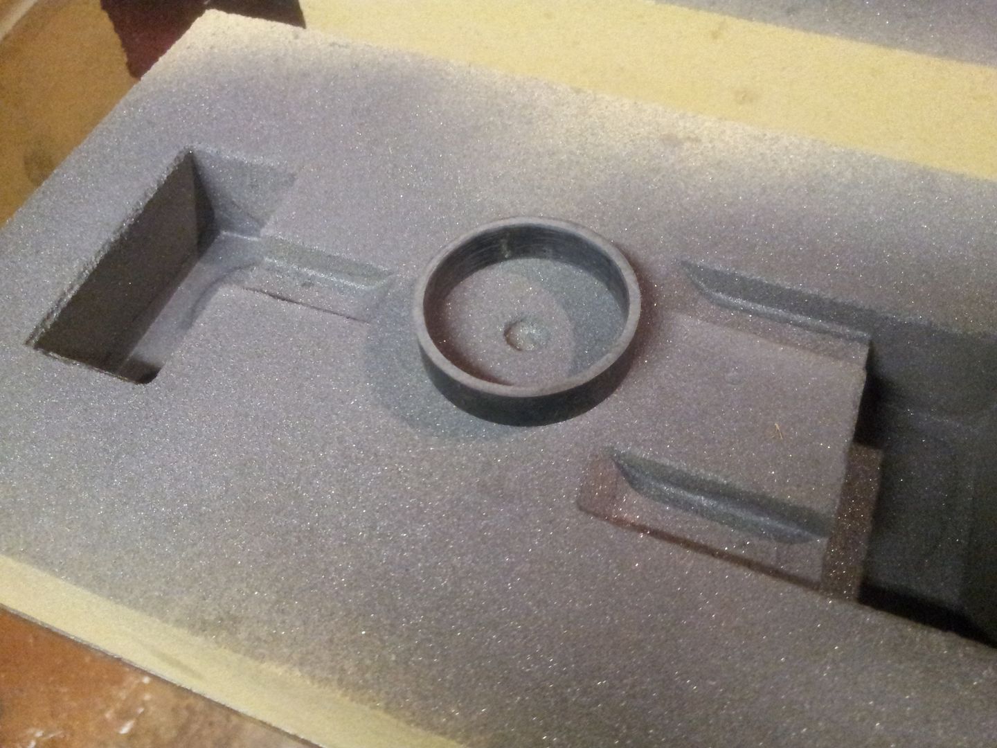 Cable ties are used to keep ring closed while filling, its gassed and removed, 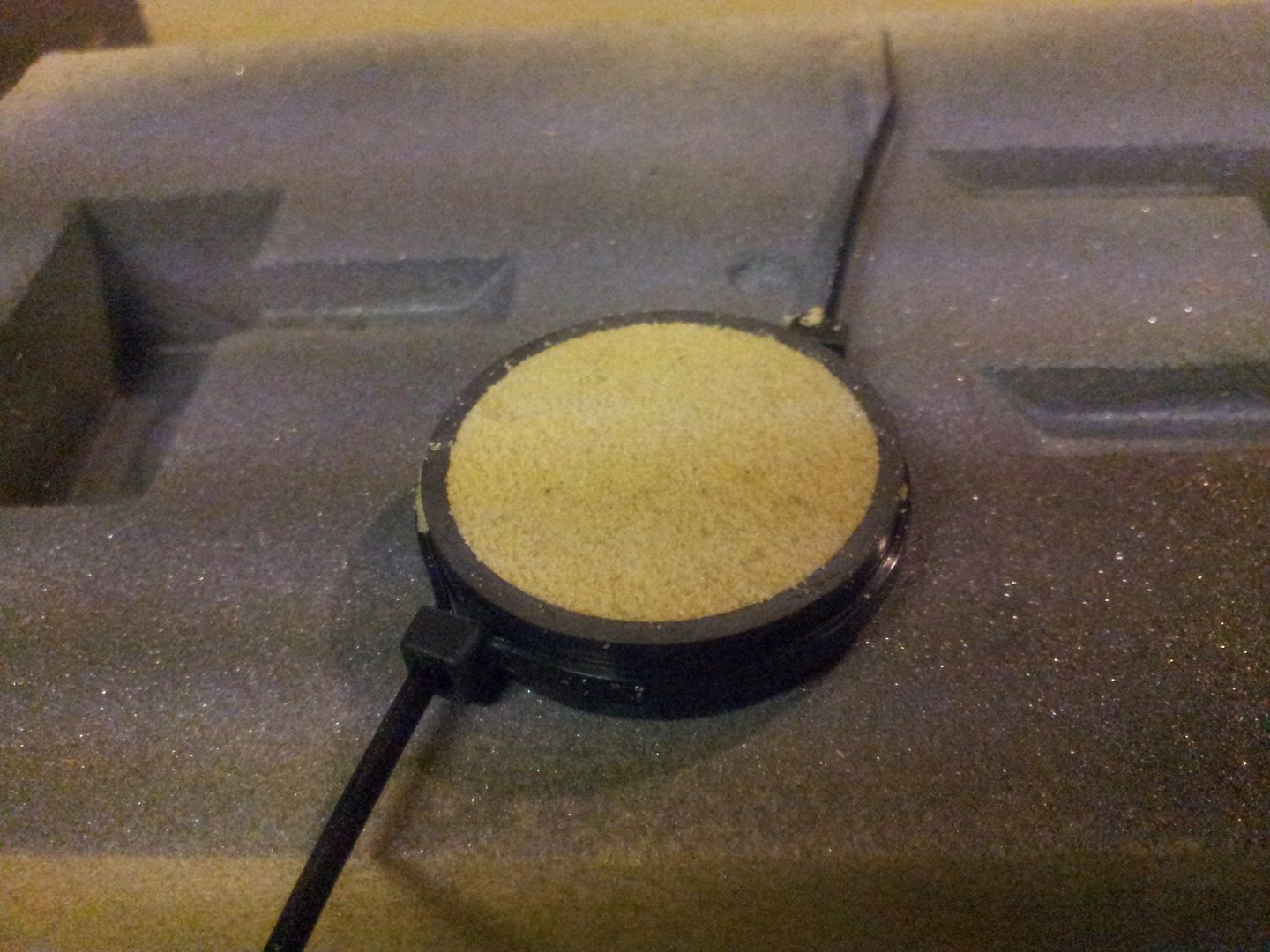 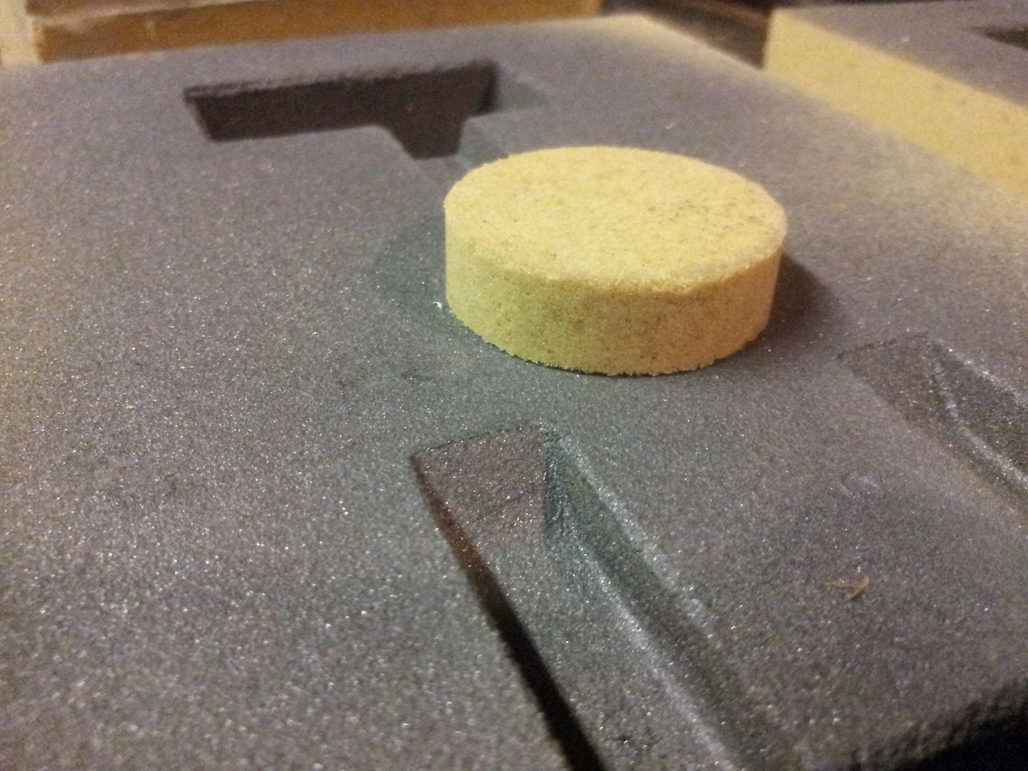 Another hole is drilled under where the core is glued to allow core to breath its internal gasses into main mould, 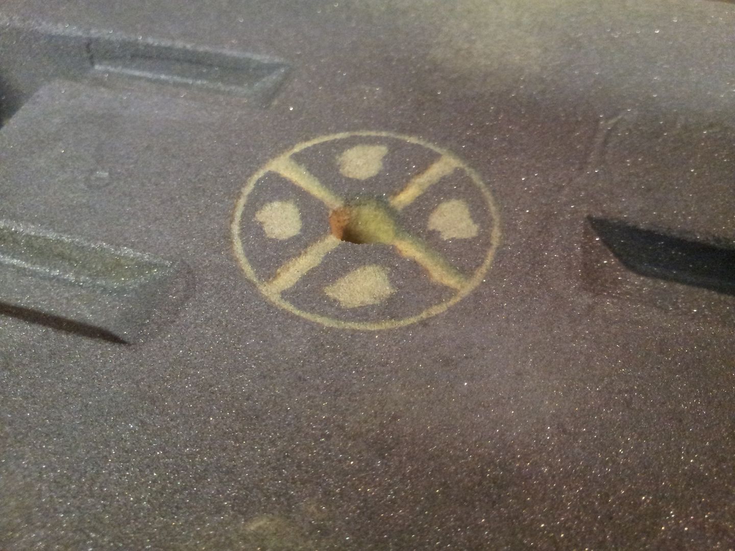 Core piece is glued on and smoothed with graphite/zircon filler, 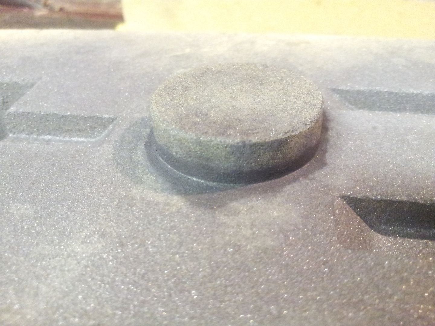 The crucible is charged with small Lm25 alloy ingots, 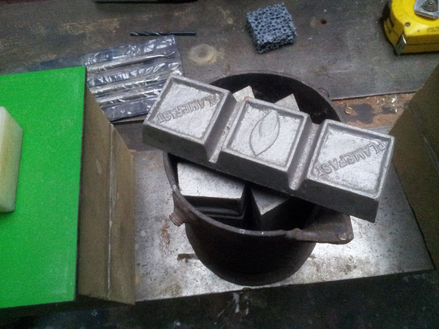 The moulds are moved to fire board on floor and purged with argon and blocked off, 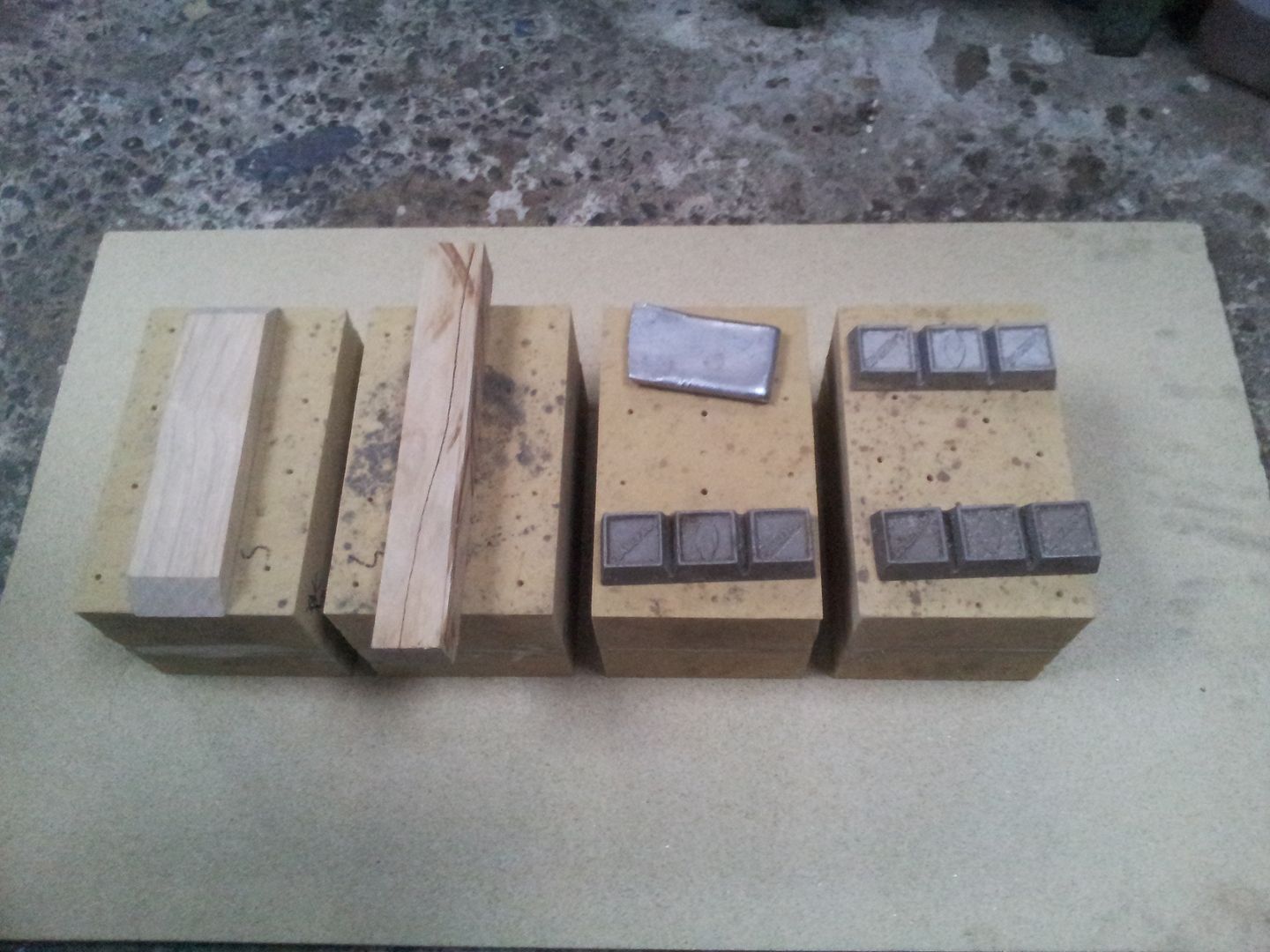 Cosy, 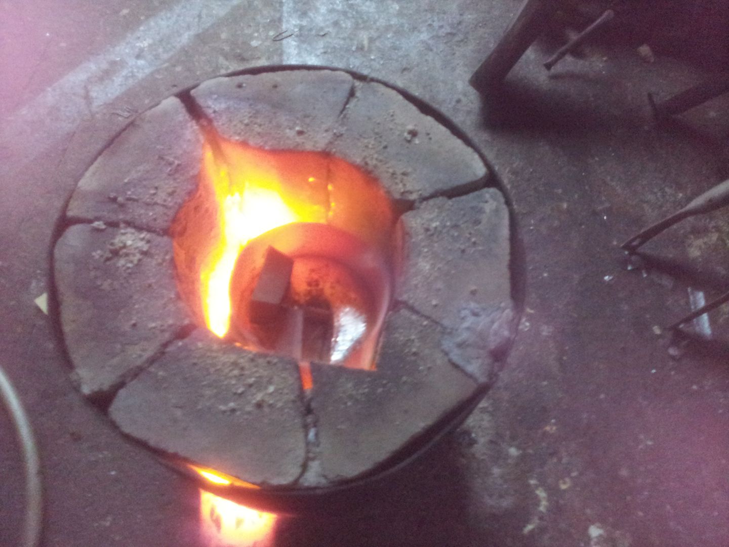 Towards the end the melt gets a flux pellet to bring any impurities to the top - stirring or touching the melt excessively is bad, you should only really touch it once to drag off dross before pouring in order to leave surface skin intact and therefore protecting the melt from gasses in the atmosphere, 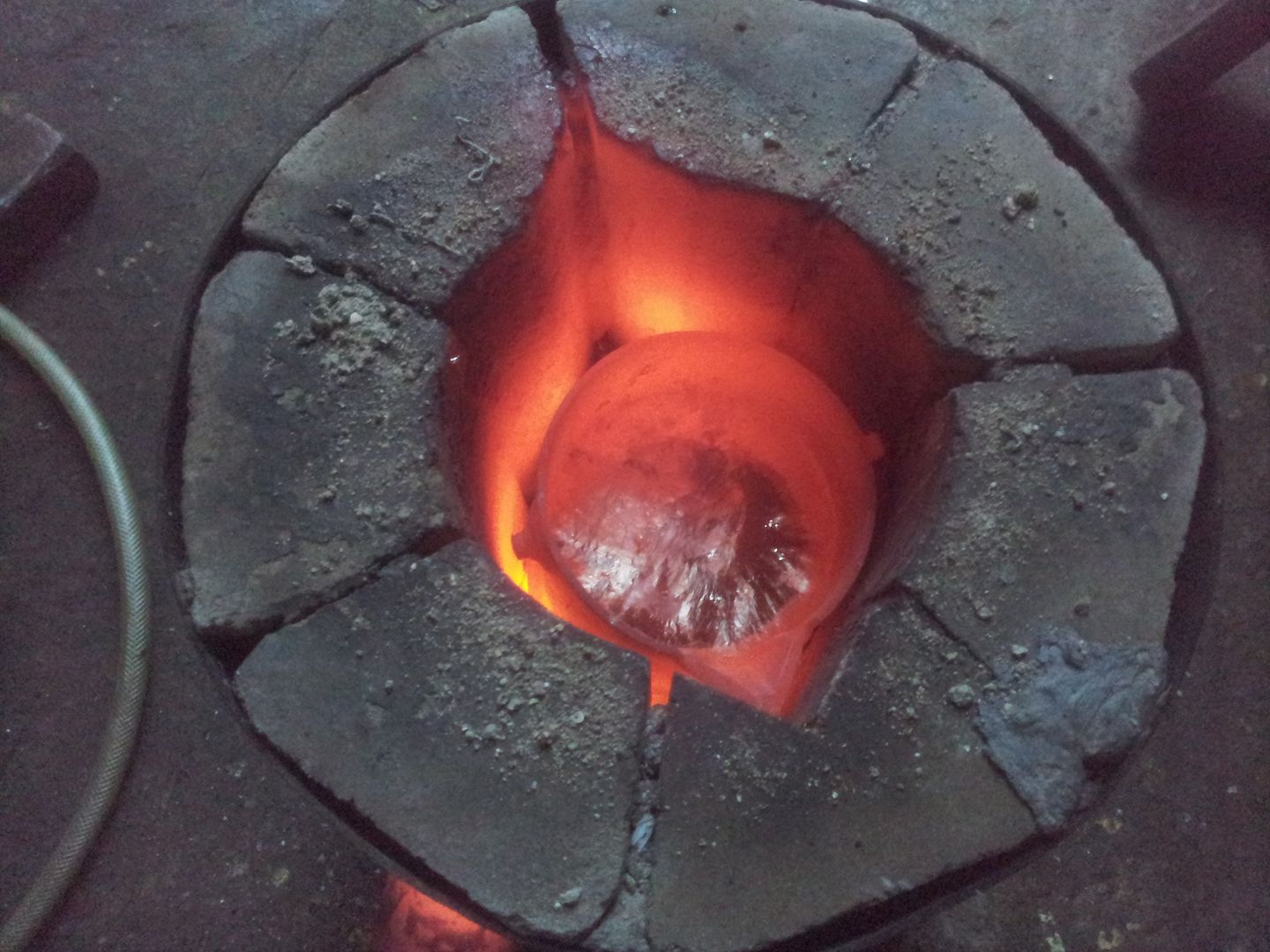 A shot right after pouring, heat causing lines on camera, 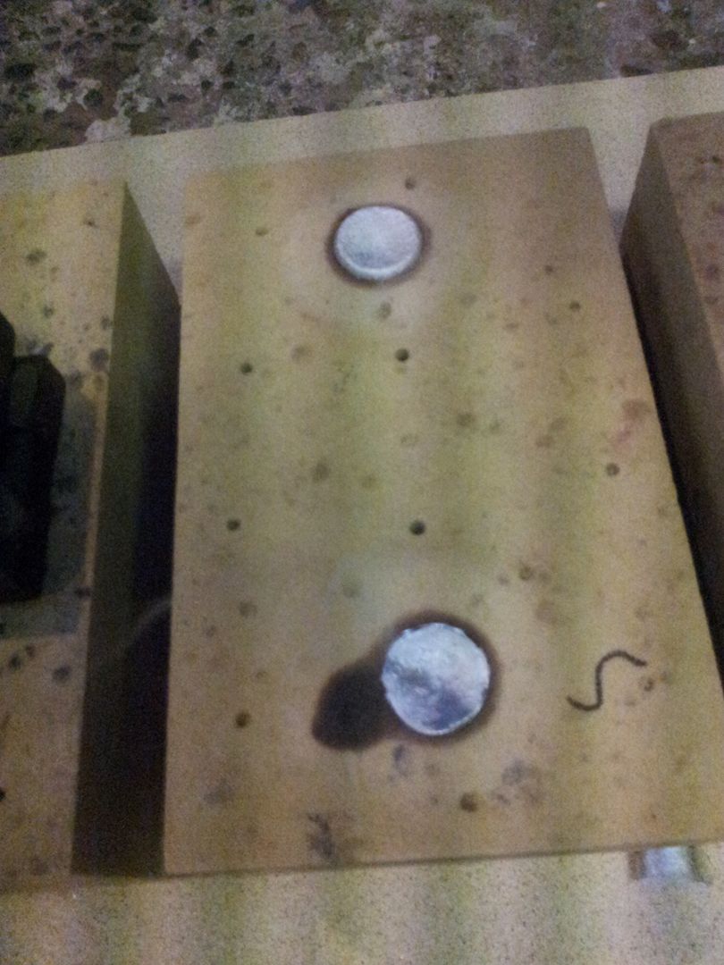 After 3min or so the moulds get cracked off with a chisel, no matter how many parts you cast, seeing a newly cast part appearing from the sand is always an amazing sight,  The vents doing their job, 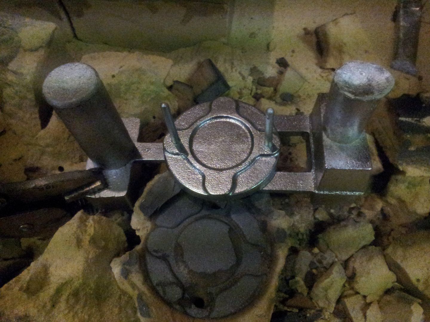 The 3 bolt covers - these were cast face down to allow metal to flow correctly around face - it also means the core can act as a vent at the rear(now the top), keeping the front face unblemished, 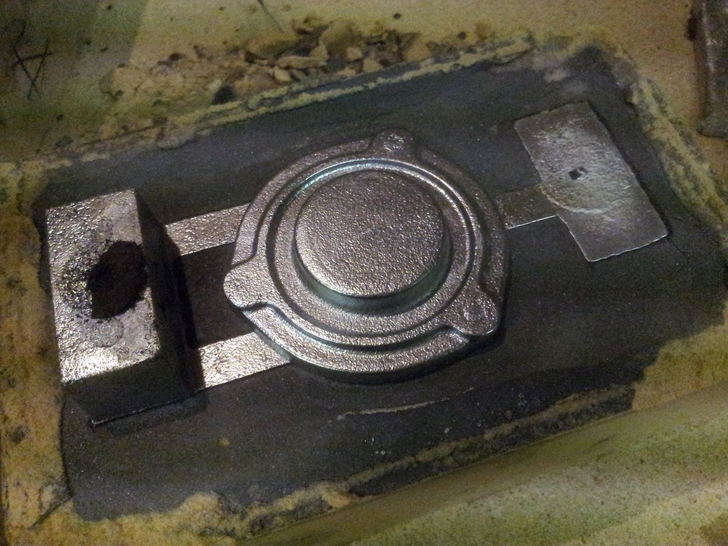 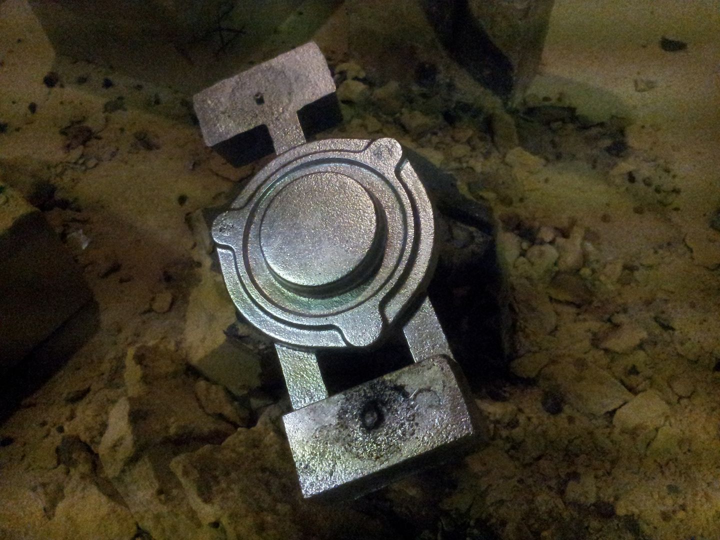 The recess, 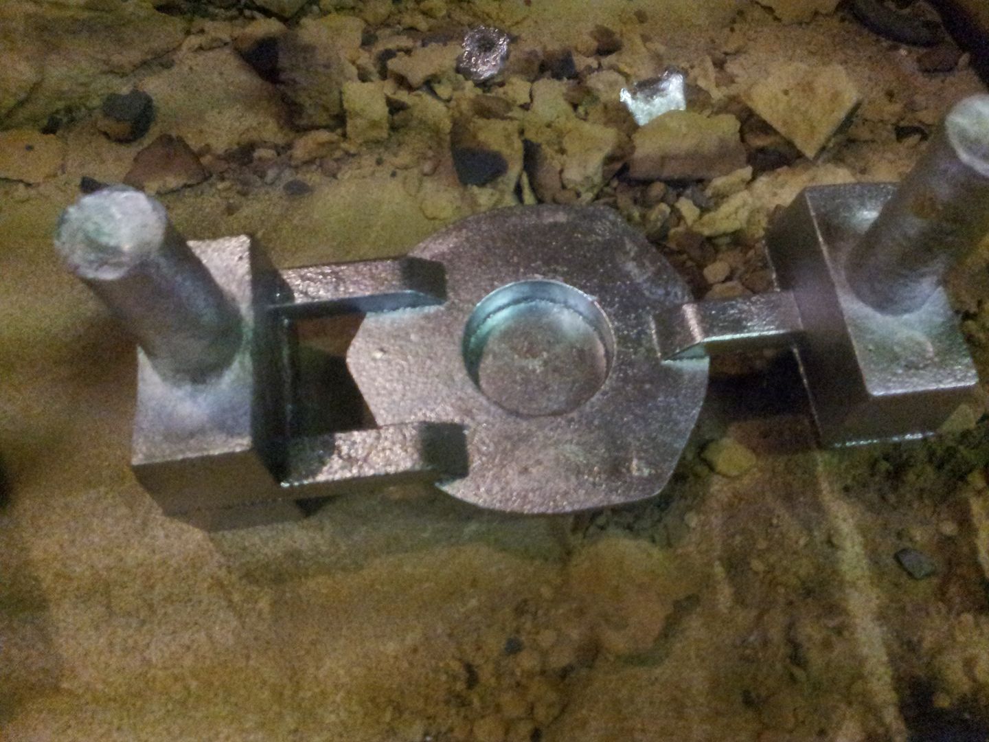 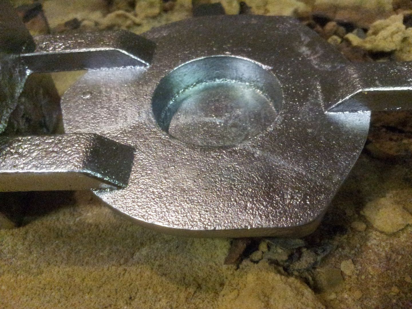 Closeup of surface finish - I think just one set will do as these are pretty bang on it terms of matching OEM finish, 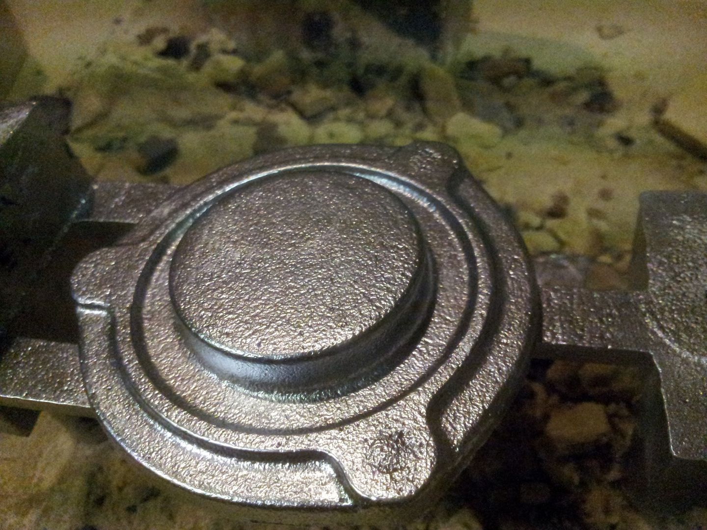 Group shots, risers + sprues now chopped off. If you look carefully, you can see a tiny nick on the top edge of parting plates - this allows me to know and keep all the 'top' orientations correct from the drawings, to the parting mould plates, and thus onto the parts themselves. This is important as once on the mill I need to be sure the raw castings are orientated as they are on the screen from which I machined the patterns from. Im not sure if the holes are on the same location/pcd, but constantly knowing the 'top' of part means it doesn't matter. 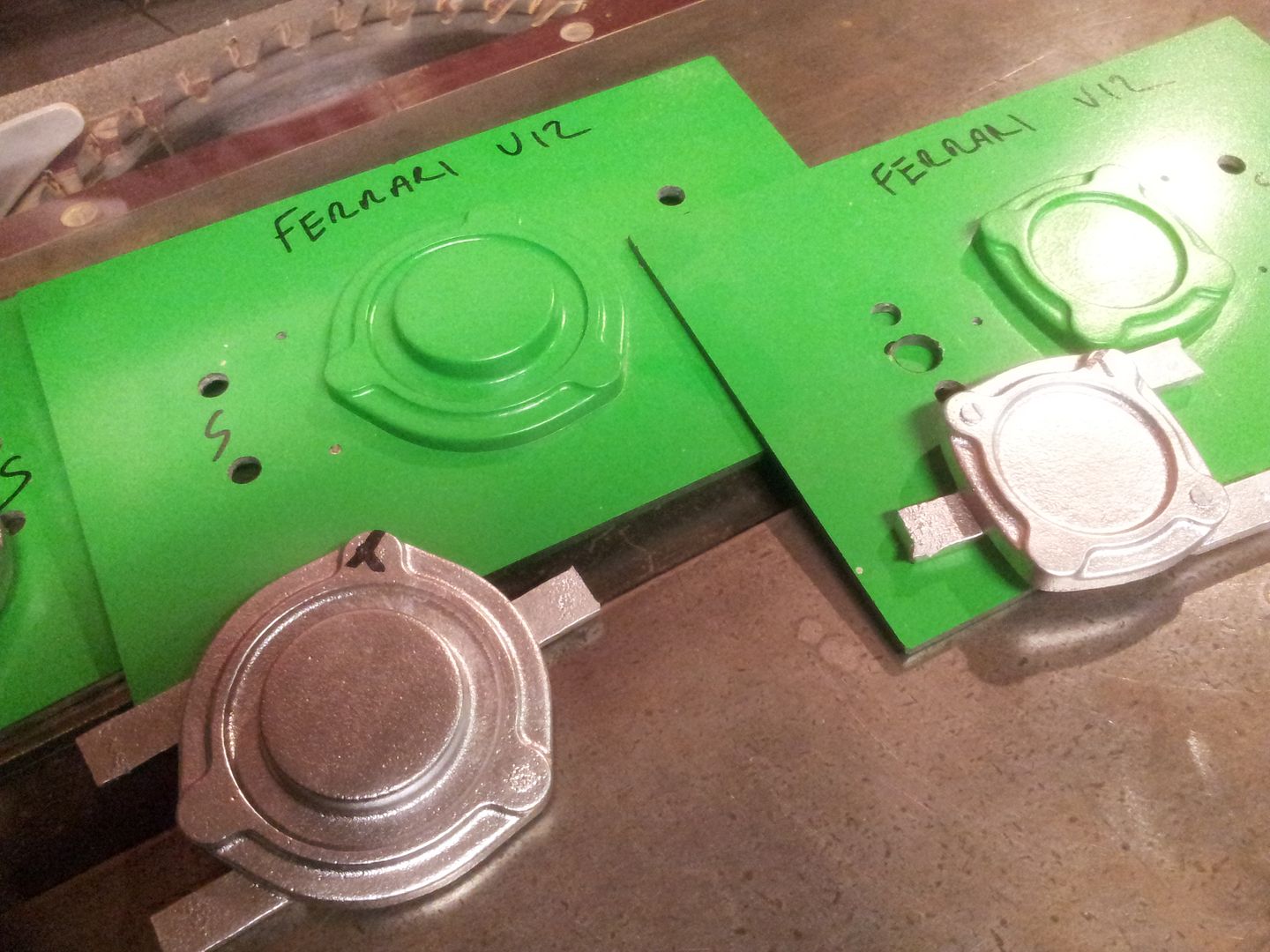 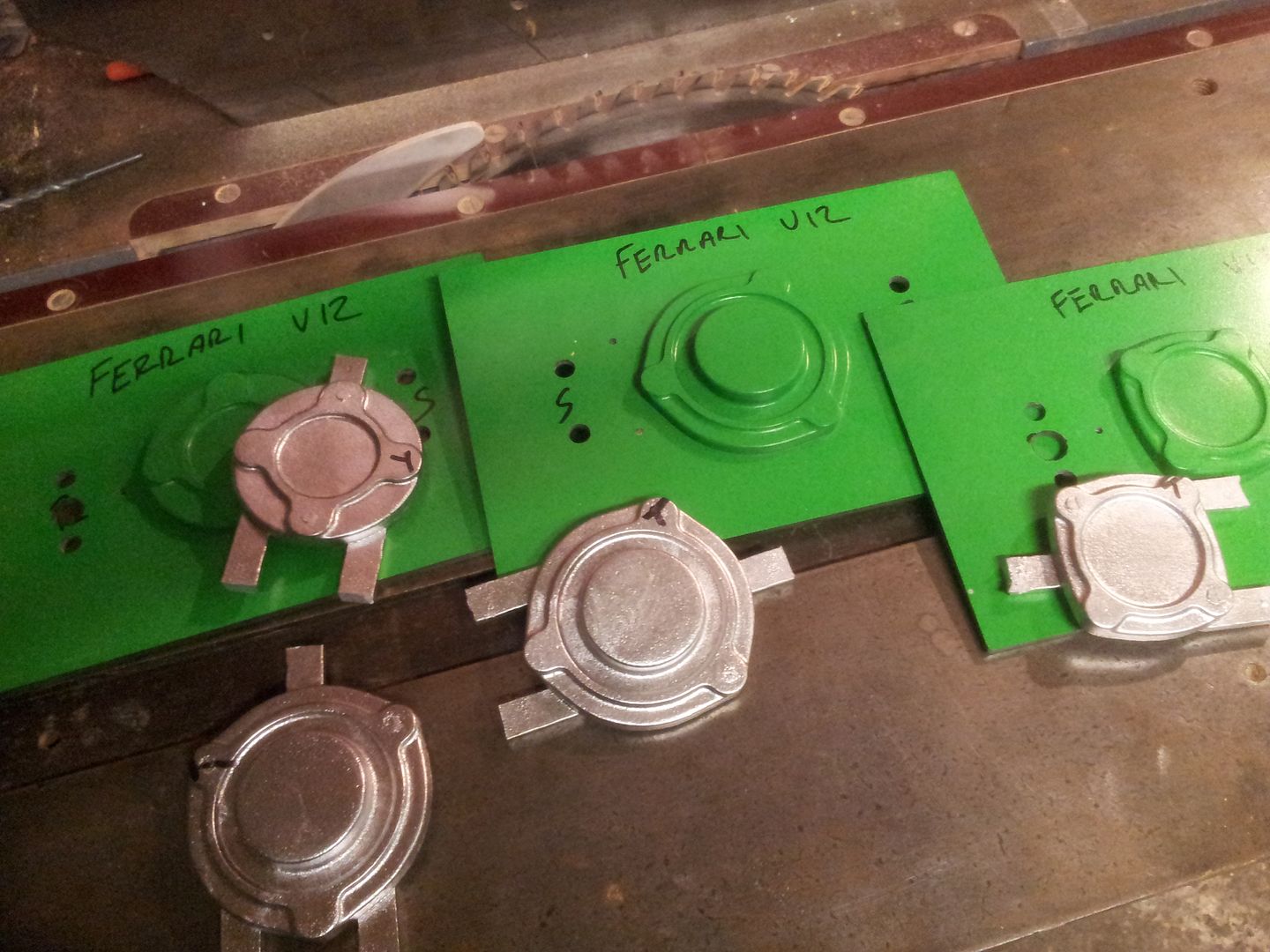 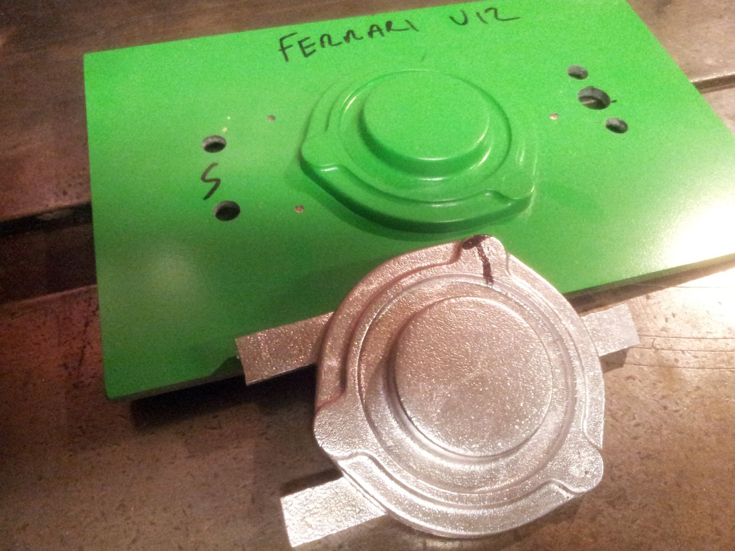 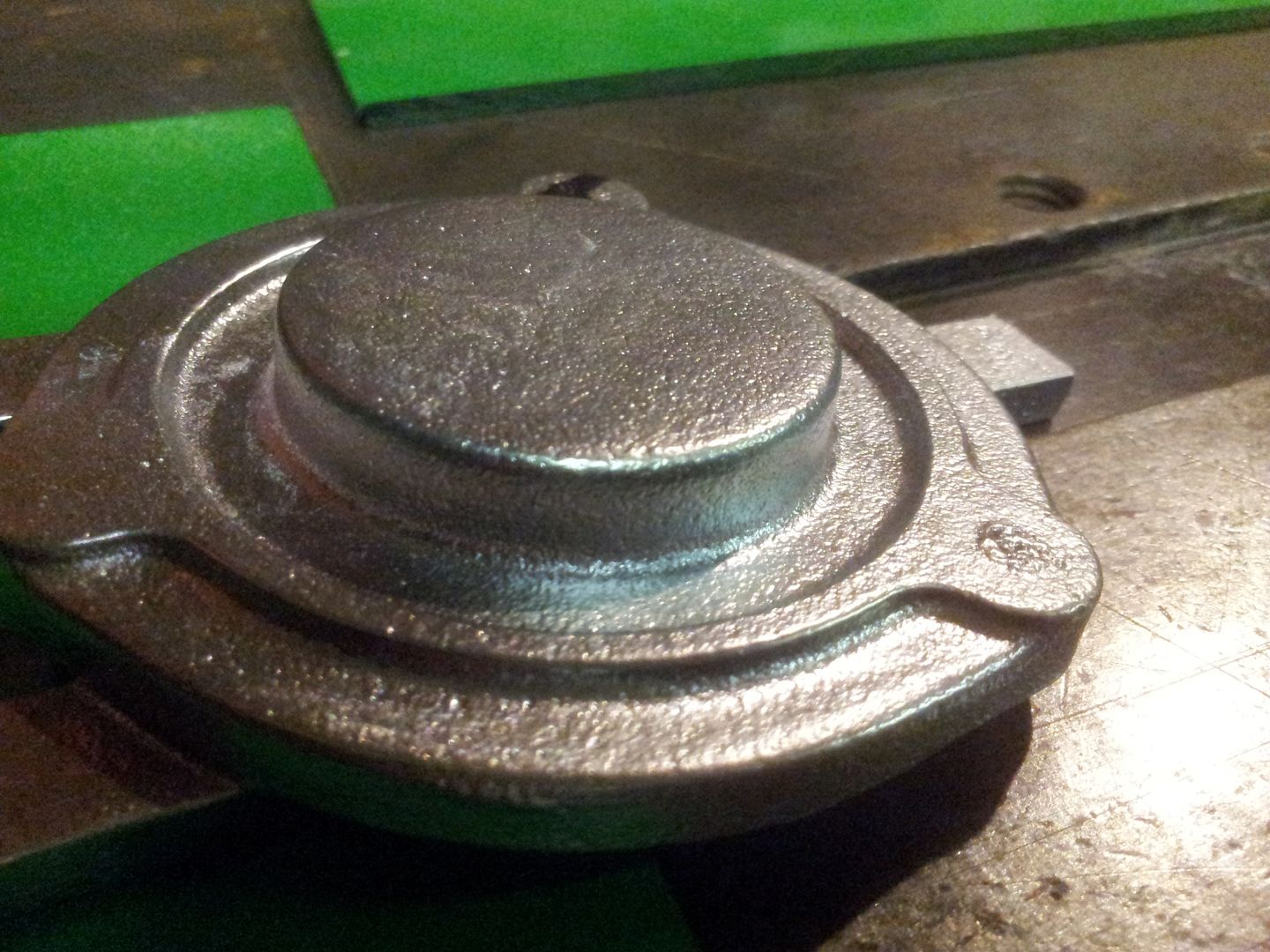 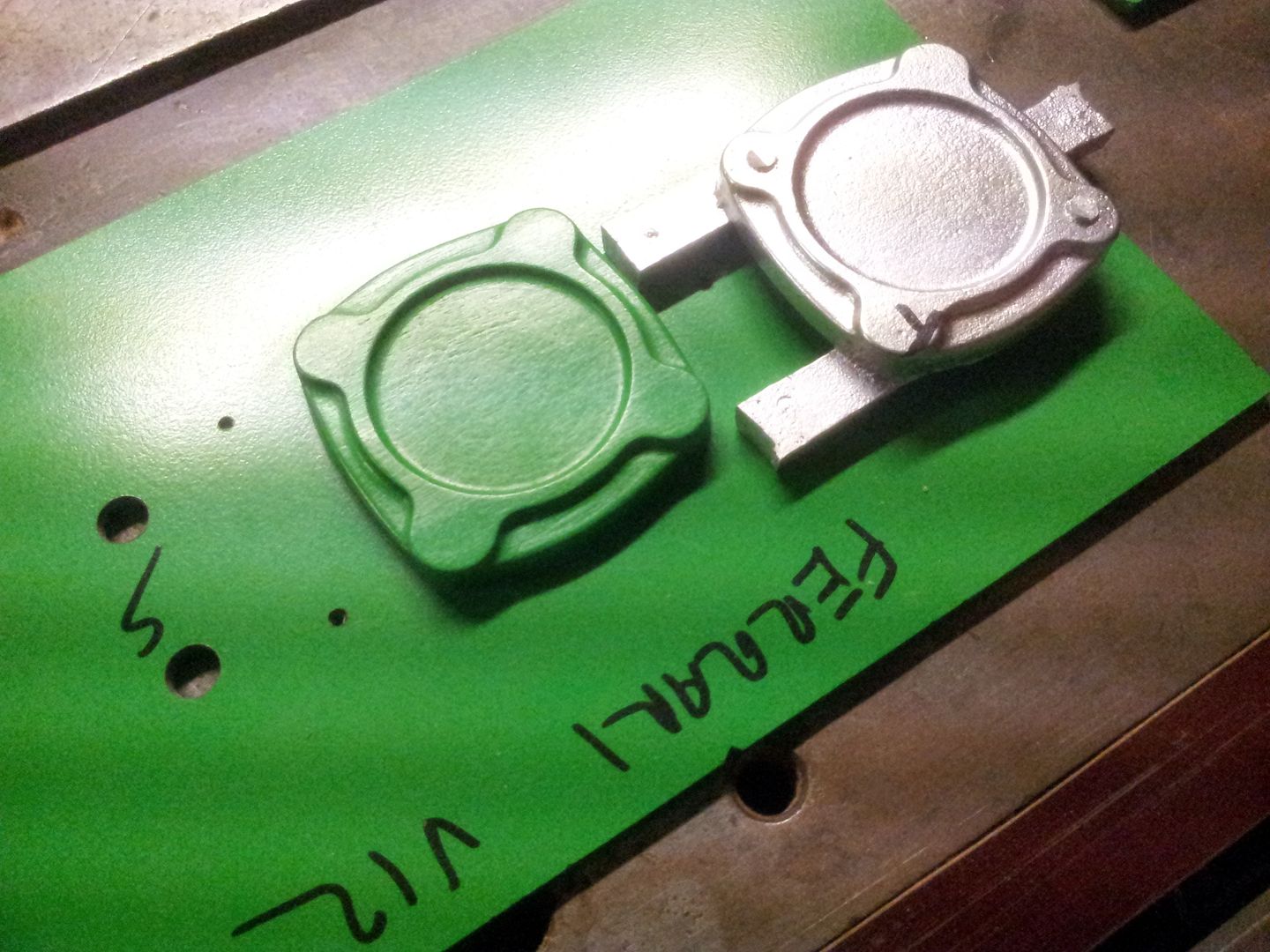 Parts will get a wash now to remove any sand left on and then get milled shortly, Brian, |
|
| Author: | mk e [ Wed Feb 11, 2015 4:49 pm ] |
| Post subject: | Re: Casting Marks Engine Parts |
Those parts look AWESOME! Great work Brian! |
|
| Author: | Brian.G [ Thu Feb 12, 2015 12:05 pm ] |
| Post subject: | Re: Casting Marks Engine Parts |
mk e wrote: Those parts look AWESOME! Great work Brian! They are ok for moulds that not too much moulding science went into. Onto machining, I left approx .7mm on the faces that needed machining. A jig was made up with a cutout to fit part outline - the three legs that were the gate/runners on part were drilled and the jig plate tapped to bolt parts from underneath, The top faces on all got machined flat and then 5mm holes drilled - the actual holes size is 7mm but these 5mm holes get tapped first for fixing parts while machining rear face flat, 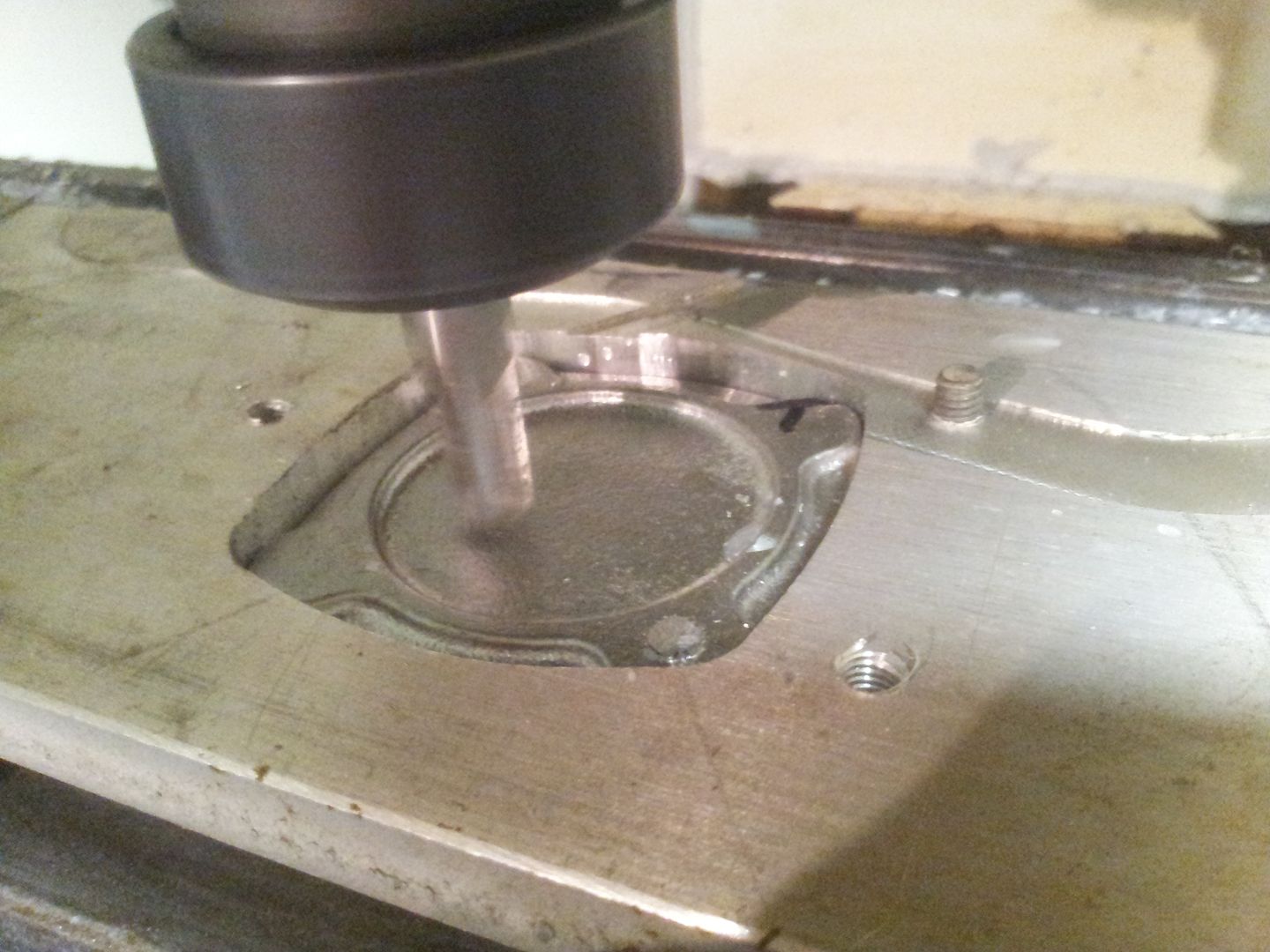 Flat, 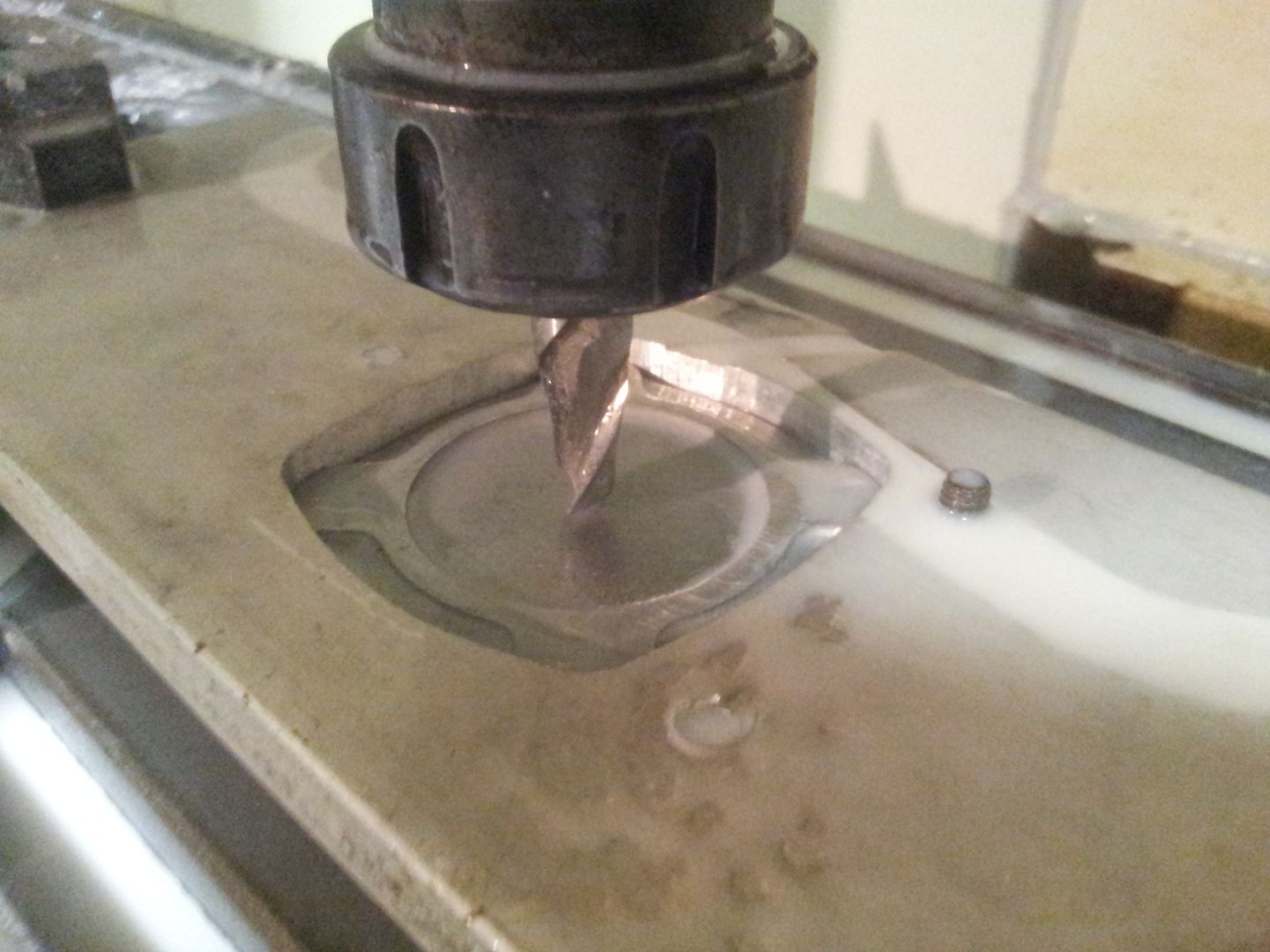 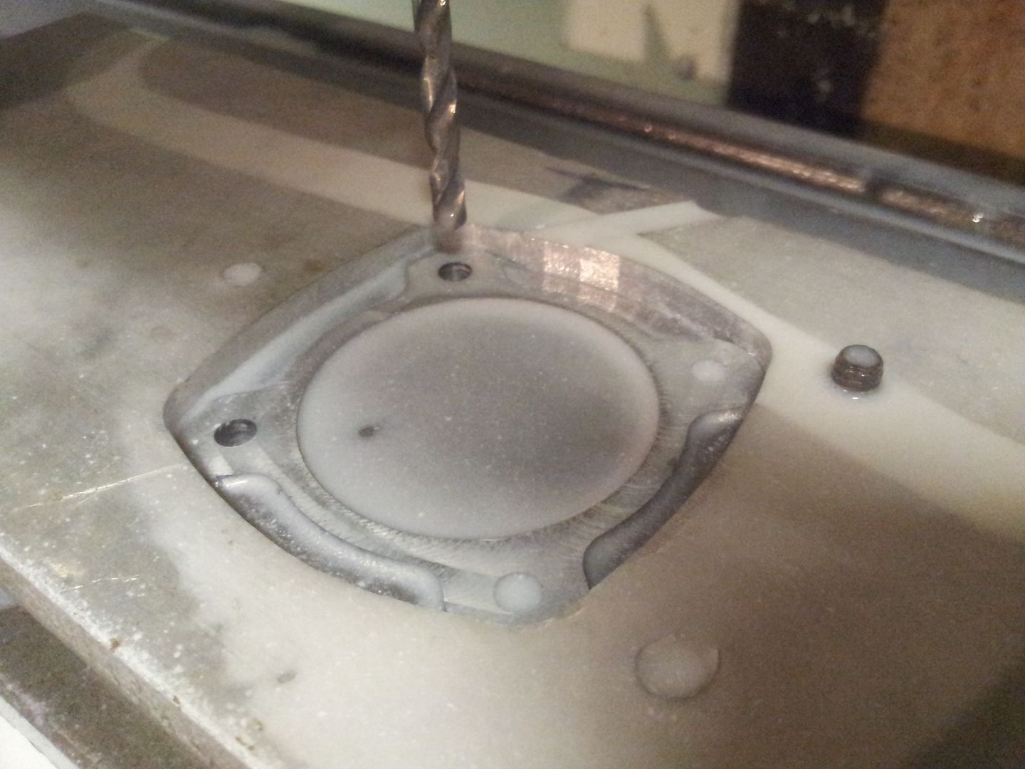 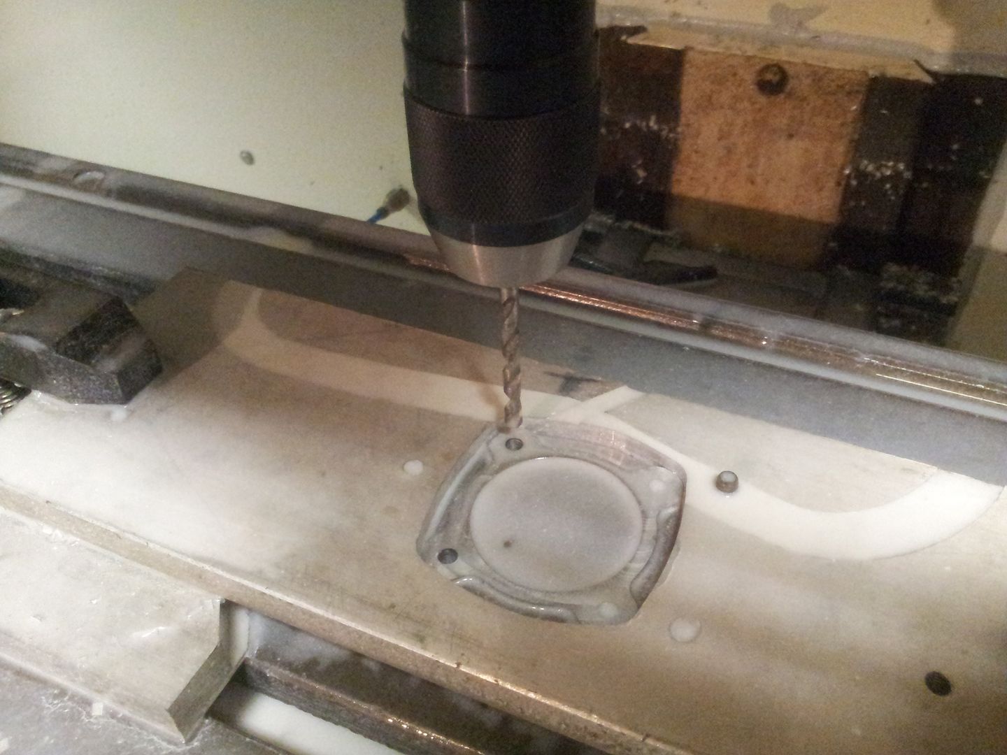 Part removed, to save jig materials the pocket was milled out to fit the next part, 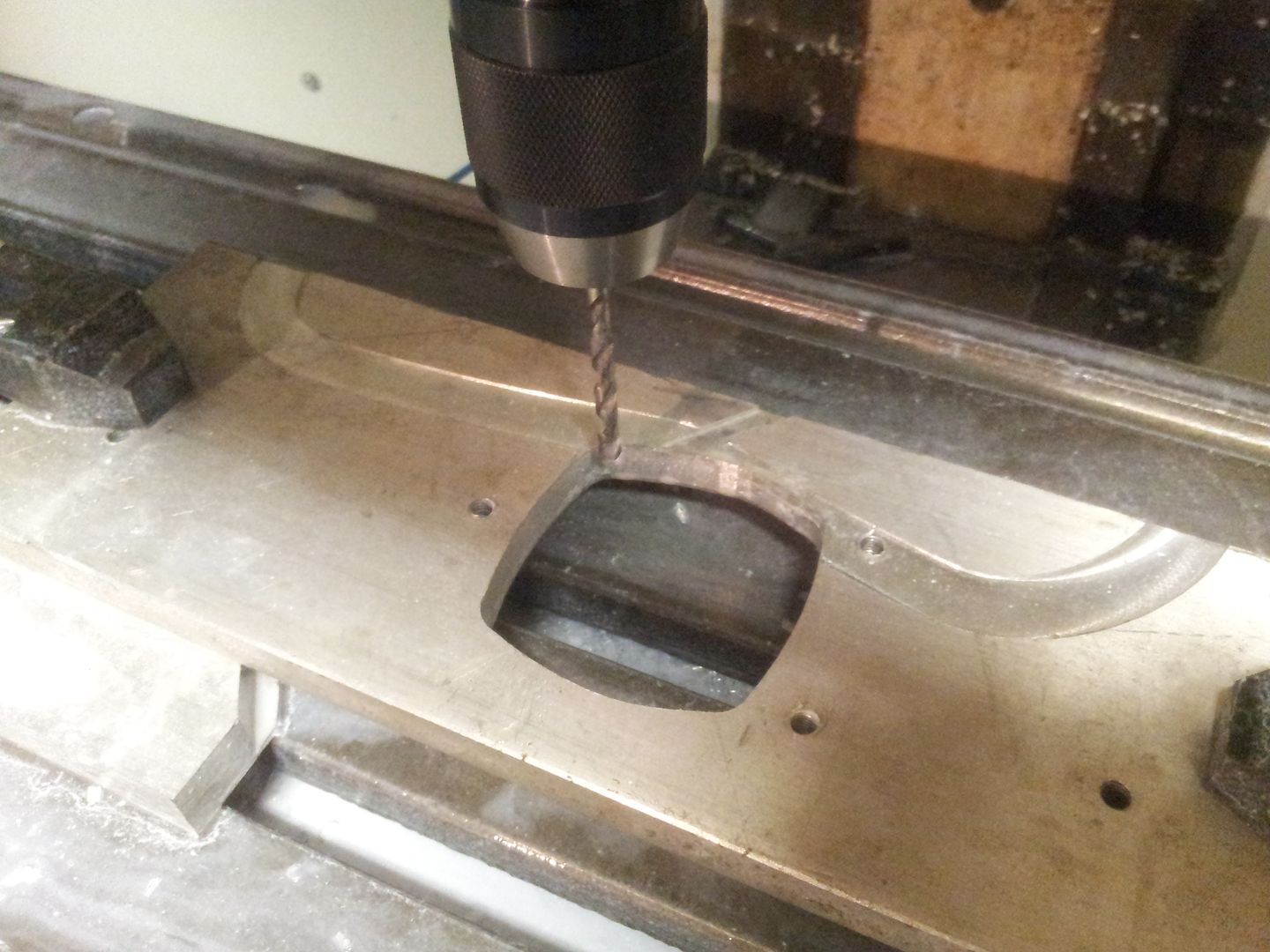 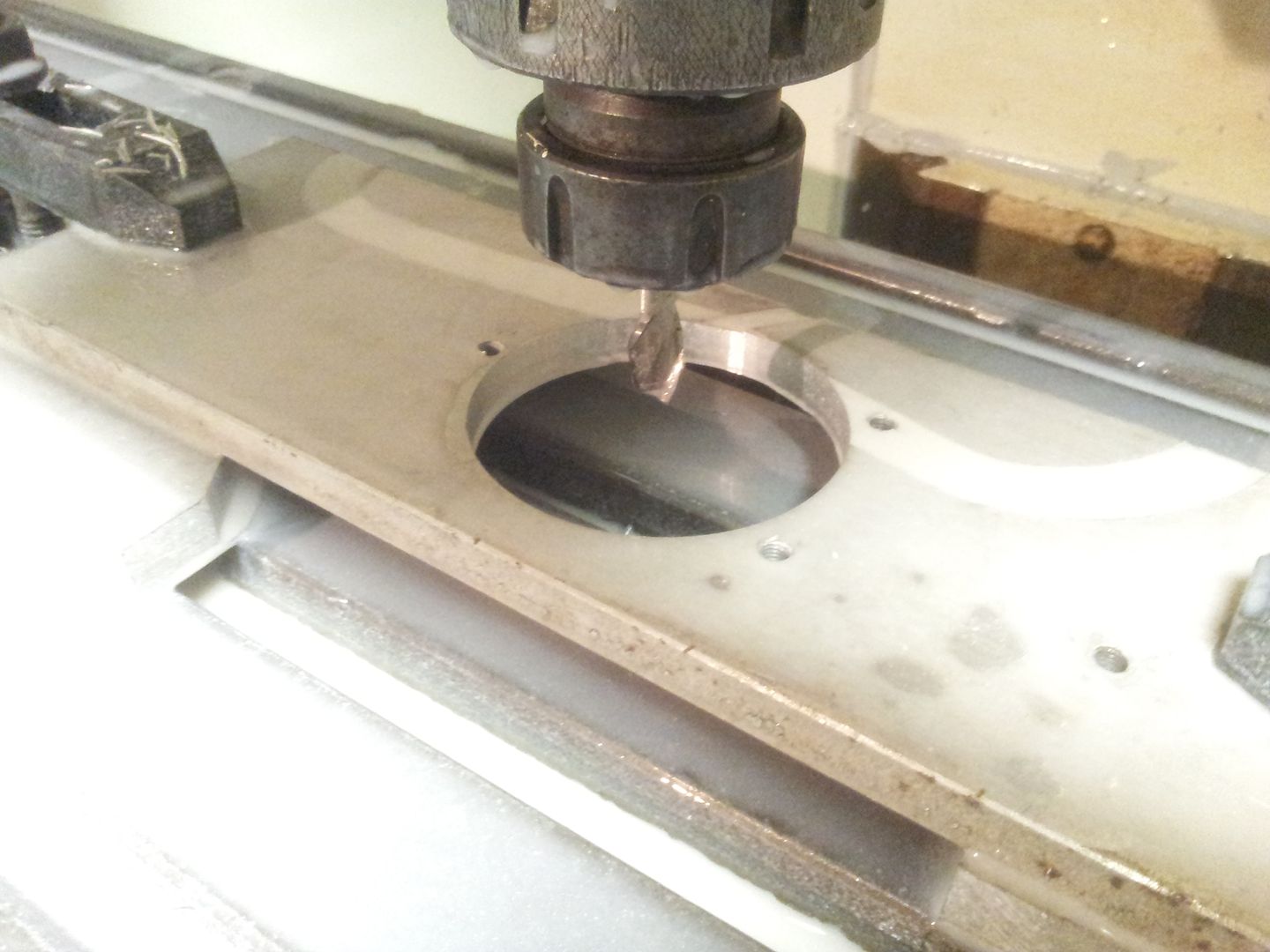 And again with the largest three bolt parts, 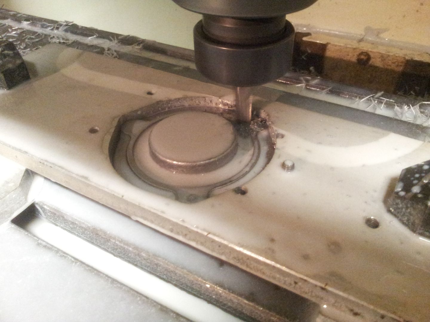 I seem to have not uploaded the rear side milling - will figure out where they went and re-upload shortly Brian, |
|
| Author: | Brian.G [ Thu Feb 12, 2015 4:40 pm ] |
| Post subject: | Re: Casting Marks Engine Parts |
Thought I had more shots of the rear machining but it seems not, Anyway, heres a bad one - lighting not yet installed in new cabinet so... Parts were bolted down rear side up on a piece of ground jig plate and machined, thread holes were then bored out to finish size once bolts were removed. 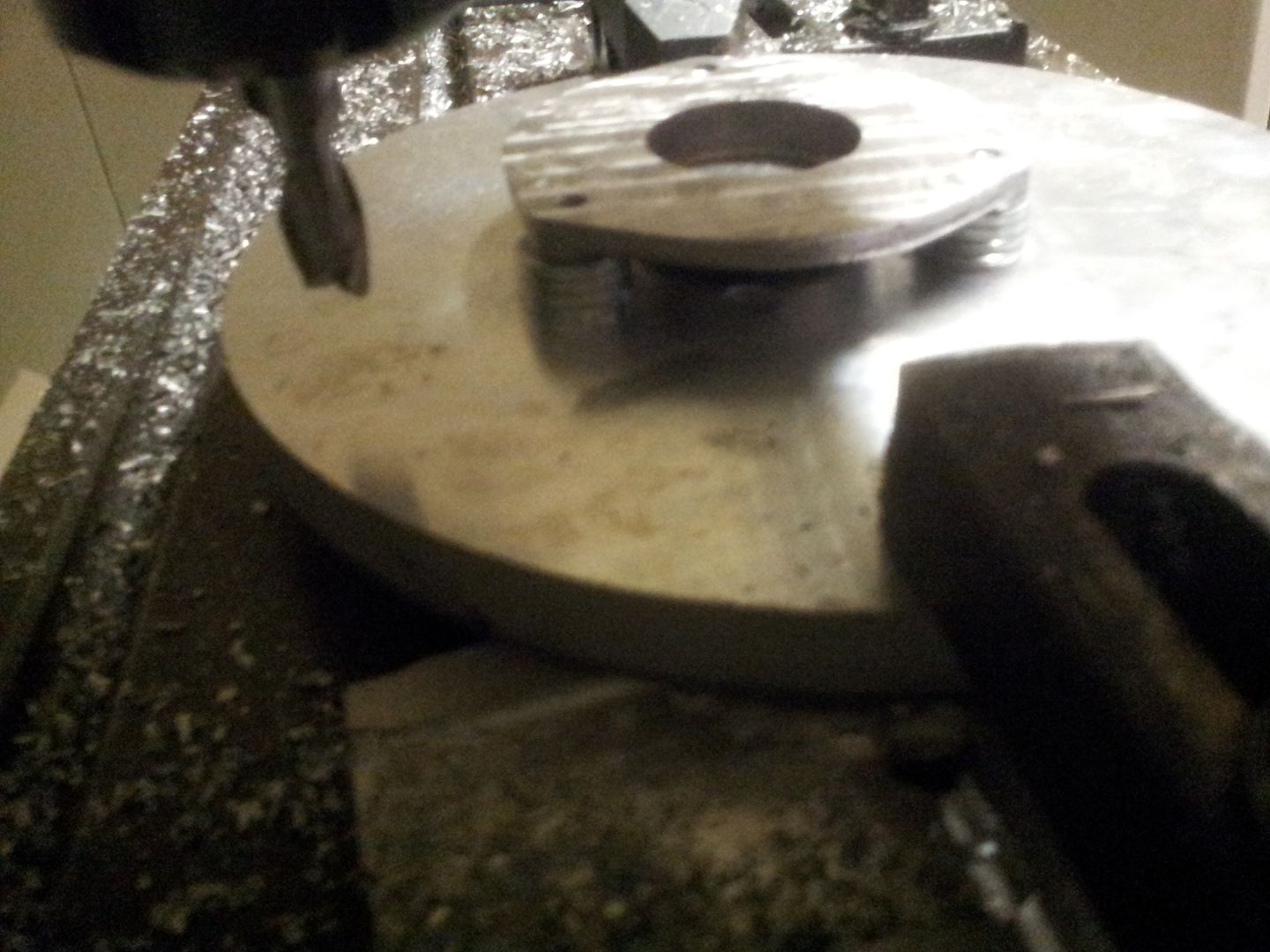 All done and packaged ready to go, you would normally bead blast after all is done to make all surfaces a uniform sheen and to remove any smut/smoke lines but since I don't do that in house I'm not willing to send just 4 parts out as the logistics wouldn't make it worth while. They are pretty good right from moulds. 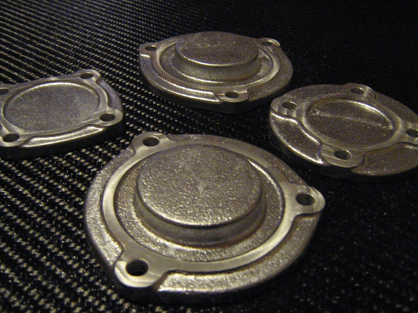 So.......thats how you make cast parts for a Ferrari V12 engine! Brian, |
|
| Author: | mk e [ Thu Feb 12, 2015 4:51 pm ] |
| Post subject: | Re: Casting Marks Engine Parts |
They look fantastic....great work Brian! |
|
| Author: | Brian.G [ Thu Feb 12, 2015 4:54 pm ] |
| Post subject: | Re: Casting Marks Engine Parts |
mk e wrote: They look fantastic....great work Brian! Thanks Mark! A pleasure, Ill shut up now and go back to quietly viewing from sideline Brian, |
|
| Author: | PSk [ Fri Feb 13, 2015 6:04 am ] |
| Post subject: | Re: Casting Marks Engine Parts |
Beautiful Pete |
|
| Page 5 of 7 | All times are UTC - 5 hours [ DST ] |
| Powered by phpBB® Forum Software © phpBB Group https://www.phpbb.com/ |
|