gemellocattivo.com

Which means "Evil Twin". Lets see your projects where you change boring into fun or create the fun from scratch.
It is currently Thu Apr 25, 2024 1:26 pm

All times are UTC - 5 hours [ DST ]


Post new topic Reply to topic  [ 2206 posts ]  Go to page Previous  1 ... 66, 67, 68, 69, 70, 71, 72 ... 221  Next
Author Message
PostPosted: Fri Nov 13, 2020 8:09 pm 
Offline

Joined: Sat Jan 03, 2015 12:49 am
Posts: 23
Wow. You look like you're getting close. So many minor (doesn't look like minor, but they are) bugs.

Art


Top
 Profile Send private message  
 
PostPosted: Sat Nov 14, 2020 1:32 pm 
Offline

Joined: Thu Jan 01, 2015 6:47 pm
Posts: 4256
2000yellow360 wrote:
Wow. You look like you're getting close. So many minor (doesn't look like minor, but they are) bugs.

Art


And here's some more. Way back I damaged a couple clips inside the main ECU connector so today was replace the connector day father than start adding more wires to the broken one, still there were about 50 to move :o


Attachments:
20201114_121737-resized-1024.jpg
20201114_121737-resized-1024.jpg [ 357.27 KiB | Viewed 3604 times ]
20201114_100636-resized-1024.jpg
20201114_100636-resized-1024.jpg [ 317.71 KiB | Viewed 3604 times ]
Top
 Profile Send private message  
 
PostPosted: Sat Nov 14, 2020 1:54 pm 
Offline

Joined: Thu Jan 01, 2015 6:47 pm
Posts: 4256
Probably a good chunk of the the rest of the day will be new wires. The expander needs its 12 MAP signal lines for starters and I'm not even sure what all the wires in the cabin are all about , clearly I was plotting something 5 years ago.

I am a little proud of myself for planning the CAN expander.....there was a bundle with all the power, ground signal all run and labeled.

Attachment:
20201112_175321.jpg
20201112_175321.jpg [ 355.5 KiB | Viewed 3605 times ]


All the wire I used everywhere is aircraft grade and all the analog signal lines are shielded, which slows things down a bit. Its a bit harder to strip because its fine strand and each strand is cad plated so you need to be really careful not to nick them....I use a thermal stripper

Attachment:
20201112_181307.jpg
20201112_181307.jpg [ 356.08 KiB | Viewed 3605 times ]


Then on the shield stuff the shielding is braided so it needs to be unbraided and either twisted and run to ground (I ground the ecu end, never ground both ends) or they make these cool connectors that heatshrink and then solder themselves when you get them hot enough, which only works with tefzel aircraft wire, pvc auto wire would catch fire. The solder area changes from red to clear when the solder melts so you know its done and the heatshrink seals so moisture can't get in....pretty cool but it take time to do.

Attachment:
20201112_193936.jpg
20201112_193936.jpg [ 189.15 KiB | Viewed 3605 times ]


Top
 Profile Send private message  
 
PostPosted: Sun Nov 15, 2020 9:30 am 
Offline

Joined: Thu Jan 01, 2015 6:47 pm
Posts: 4256
Finished wiring in the MAP wires yesterday but couldn't get the damn thing working....played with every setting....moved it to CAN B......went inside and had drink. This morning I remembered that early on I'd mistakenly type the CAN addresses in HEX and the letter part was accepted...hmmm...I wonder....yeah, changed the addresses from decimal to HEX and I have 12 MAP readings. The way the board works the 12 readings are not truly independent even thought there are 12 sensors, but its easy to see the 0-10% error mistuned TBs would make and larger errors also show just not in a simple linear way, and because this is a board thing the old way I was getting the signals would have the same issue.

A couple little things to fix in the model and display but its mostly working now....at least with a brake bleed pump hook up to pull vacuum, still need to see what it does on a running engine.


Attachments:
20201115_080250-resized-1024.jpg
20201115_080250-resized-1024.jpg [ 201.27 KiB | Viewed 3588 times ]
Top
 Profile Send private message  
 
PostPosted: Sun Nov 15, 2020 2:48 pm 
Offline

Joined: Thu Jan 01, 2015 6:47 pm
Posts: 4256
On that whole 2 steps forward 1 step back path getting the cylinder reading working made me realize the multiMAP itself was really working right. When I saw the output didn't match the lowest cylinder I quickly told myself and all of you that's normal....no its not.

Attachment:
multiMAP.JPG
multiMAP.JPG [ 169.27 KiB | Viewed 3580 times ]


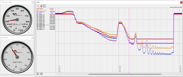
The blue is MAP1 voltage, which I confirmed with a meter, its right. The purple is the multiMAP output, it doesn't track right and never goes below 1.3V, but by 1.4V its not longer tracking right at all, so while it could read to about 37kPa, 40 kPa it had really lost any hope of calibration.

hmmmmmm........Pulled the wire out of the ECU connector and check with a meter...same answer

hmmmm......where's the circuit drawing, this is normally where I get myself into trouble because, yeah, I suck at electronics, but not today. The analog inputs on the ECU all have a 100k 5V pullup so when they are not connected to anything they read 5V which while often very helpful its buggering my NBO2 sensor reading and I thought maybe this too......but no. What's buggering this is the isolation amp, its apparently not setup right and doesn't have the correct range.. But, this thing is a pretty dead simple analog circuit, I just moved the output wire to bypass the amp and its pretty much fixed. Now I'm pretty sure the 5V pullup is causing voltage reading not to drop quite as low as it should, but that I can and did calibrate and now the MAP is about 1.5kPa above the cylinder reading at atmosphere, and about 1kPa high at the most vacuum I could pull....plenty close enough (red and orange lines)


Attachments:
circuit edit.JPG
circuit edit.JPG [ 129.49 KiB | Viewed 3580 times ]
multiMAP fixed.JPG
multiMAP fixed.JPG [ 161 KiB | Viewed 3580 times ]
Top
 Profile Send private message  
 
PostPosted: Sun Nov 15, 2020 6:28 pm 
Offline

Joined: Thu Jan 01, 2015 6:47 pm
Posts: 4256
Trying to work through some of these wires.

I connecter the rear axle speed....it reads the speedo sensor and that end was wired, now it goes to the ecu.

Looking up front I see a couple long 3 conductor wires...must be wheel speed, easy. there are 3 2 conductor....I'll make one CAN to make future work easy, you know, now that I'm a CAN system master :)

my wiring pinout shows white/yellow as the "slow down" light

I show a clutch and brake pedal, I probably thought they would be good for traction and/or launch control....a couple of the orange wires I guess.

Then another 3 wire labeled steering so it looks like I was planning to add a steering angle/position sensor for logging I guess I was thinking. anyone have a good (aka low cost) solution for steering position?

This stuff takes forever....


Attachments:
20201115_170140-resized-1024.jpg
20201115_170140-resized-1024.jpg [ 281 KiB | Viewed 3581 times ]
Top
 Profile Send private message  
 
PostPosted: Mon Nov 16, 2020 10:52 am 
Offline

Joined: Thu Jan 01, 2015 6:47 pm
Posts: 4256
Spent a bit more time on MAP sensors after weather.com told me the correct baro reading for my area was 101.5 not the 99.5 may sensors displayed....101 ish now. On the other end the sensors on the multiMAP have a min output of 20kPa while the baro goes down to 10 which let me confirm my brake bleeder pump was pulling under 20 and I could use the lower flatline as a second cal point. That all seems close enough now and much better than it all was.


Top
 Profile Send private message  
 
PostPosted: Mon Nov 16, 2020 7:31 pm 
Offline

Joined: Thu Jan 01, 2015 6:47 pm
Posts: 4256
To me the fact that a ferrari has a "Slow Down" dash light is about the funniest thing I can think of

Attachment:
20201116_180417-resized-1024.jpg
20201116_180417-resized-1024.jpg [ 251.34 KiB | Viewed 3564 times ]


The ECU now has control of that light...I've not completely decided how the ECU will use that power but it has it.  its a frikin bright light so I my do something light a dim (maybe with slow blink) is traction control active and bright flashing is low oil pressure and such.

Attachment:
20201116_180424-resized-1024.jpg
20201116_180424-resized-1024.jpg [ 239.16 KiB | Viewed 3564 times ]


I was also looking a bit at steering angle options and thinking maybe something like this from pegasus would fit up under the dash , mostly right now I want to know where the wire so I can button up the dash at some point

https://www.pegasusautoracing.com/productdetails.asp?RecID=5119


Attachments:
MC-180.jpg
MC-180.jpg [ 15.68 KiB | Viewed 3564 times ]
20201116_165553-resized-1024.jpg
20201116_165553-resized-1024.jpg [ 373.55 KiB | Viewed 3564 times ]
Top
 Profile Send private message  
 
PostPosted: Tue Nov 17, 2020 9:59 pm 
Offline

Joined: Thu Jan 01, 2015 6:47 pm
Posts: 4256
Went to hook up a couple more wires tonigh....hmmm....no pins left, at least not the pins I was looking for.

The plan now is I should be able to drive any relay with a HighSide pin, they are 12V, 2A I think, just need to rewire the relays. That will free up to 3...these are just on/off, the LowSide outputs are pwm so more valuable and what I need for the water temp gauge I was trying to connect.

I think the 2 internal throttle controllers are also available....4 pins 0/12+ and all 4 can be driven separately I think. I can't use them because they are 5A and my throttle pulls 15 so I needed an external controller and dirving it ate 2 or my LS pin, but I think I can use these for a lot of things..... probably....


Top
 Profile Send private message  
 
PostPosted: Tue Nov 17, 2020 10:52 pm 
Offline

Joined: Thu Jan 01, 2015 6:47 pm
Posts: 4256
I'll add this thought, nobody plans to fail, they simply fail to plan.....yeah.....no idea where I planned to connect all those wires....


Top
 Profile Send private message  
 
Display posts from previous:  Sort by  
Post new topic Reply to topic  [ 2206 posts ]  Go to page Previous  1 ... 66, 67, 68, 69, 70, 71, 72 ... 221  Next

All times are UTC - 5 hours [ DST ]


Who is online

Users browsing this forum: No registered users and 9 guests


You cannot post new topics in this forum
You cannot reply to topics in this forum
You cannot edit your posts in this forum
You cannot delete your posts in this forum
You cannot post attachments in this forum

Jump to:  
Powered by phpBB® Forum Software © phpBB Group