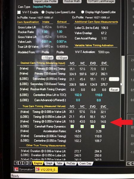
I'll share this before I start so you guys have time to stop me if you see something wrong
Time from the engine software. I
m using the marked row, true timing at .050 lift at the valve which accounts for lash, the line above is at the cam and would be how ferrari says to set timing by first setting the valve to 0 lash. The lobe are a symmetric grind, which means the lobe center, which is what I'm really setting is exactly in the middle so if I set opening and closing is off, I just split the difference and the lobe center will be correct.
Attachment:
 timing.jpg [ 496.49 KiB | Viewed 2661 times ]
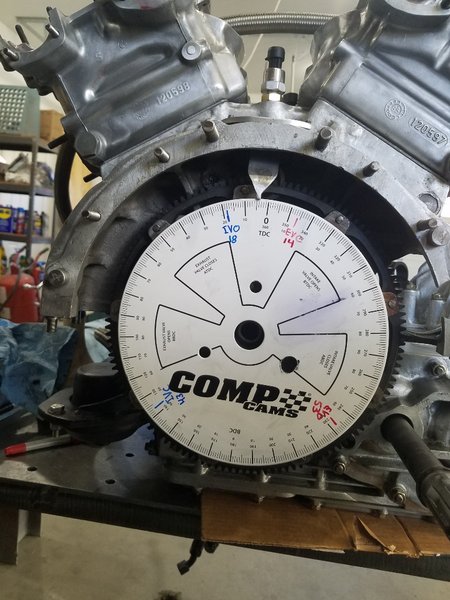
Degree wheel on and marked, blue is intake, red exhaust. My marks don't fall in the printed windows because I have the wheel on the flywheel not the damper so its backwards. This wheel is almost exactly the OD of my trigger pattern on the flywheel which I use for the ECU but also for reading timing so setting it up is as simple as stick it on with the 0 aligned with the TDC mark on the flywheel.
Attachment:
 20211114_091509-resized-1024.jpg [ 291.4 KiB | Viewed 2661 times ]
Last time I bolted it to the crank, I guess the flywheel wasn't finished? don't recall, anyway I I did bank 1 then calculated where bank 2 stuff should be and clearly buggered that math beyond belief, but this time its going to be different!....I'm just going to move the damn degree wheel and use the exact same marks. The trigger pattern is 36-1 so there is a tooth exactly every 10 degrees and the way I built is #1 TDC is exactly the center of a tooth marking #7 TCD exactly the center of the 6th tooth....no more dumbass mistakes...I hope....

