gemellocattivo.com

Which means "Evil Twin". Lets see your projects where you change boring into fun or create the fun from scratch.
It is currently Fri Dec 05, 2025 2:39 pm

All times are UTC - 5 hours [ DST ]


Post new topic Reply to topic  [ 2759 posts ]  Go to page Previous  1 ... 272, 273, 274, 275, 276
Author Message
PostPosted: Sat Nov 29, 2025 11:54 am 
Offline

Joined: Sat May 14, 2022 4:21 pm
Posts: 9
Your part looks better than anything else in the picture!


Top
 Profile Send private message  
 
PostPosted: Sat Nov 29, 2025 10:01 pm 
Offline

Joined: Thu Jan 01, 2015 6:47 pm
Posts: 4728
bda wrote:
Your part looks better than anything else in the picture!


I think that goes in the sad but true bucket :lol:

I didn't get as much time today as I hoped and things did go completely to plan. I did the final assembly and tightened everything down and notice a bit of play that clearly could not be written off as loose bolts. It turned out to be the a combination or the new double u-joint wanting a very rigid everything and the OEM column mounts having an "W" stamped into them to allow the collapsible column to work. After a bit of head scratching I decided on an additional bracket basically square to the 1st bracket. Kind of a bugger to install but its light weight and seems to have solved the issue. Yay.
Attachment:
20251129_200849.jpg
20251129_200849.jpg [ 2.86 MiB | Viewed 171 times ]


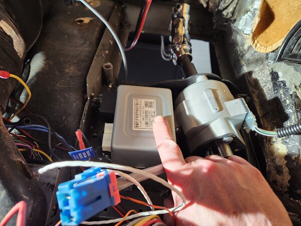
With that sorted I started thinking about mounting the controller and wiring....but didn't actually have any ambition left to actually do any of the thing I was thinking. It looks like now that the EPS motor now all up out of the footwell that is probably room for the controller to tuck right below the EPS motor
Attachment:
20251129_200936.jpg
20251129_200936.jpg [ 2.75 MiB | Viewed 171 times ]


That is I the preferer location I think because it means I don't need to extend any of the EPS harness wires...but I want to drop in the pedals and make sure its not in the way of feet. The fall back is behind the dash, but I'll figure that out tomorrow. Another wiring thing is this unit has smaller wiring than the fiesta unit.

This is a 40A fuse and the motor is rated at 400W and I know the controller puts out a max of 36A...36x12=432W or at 14V its 504W. And the 400W torque is 46Nm, but my car only needs about 1/2 that so max A draw should be about 18A@12V or 14A @14V. I could probably get away with 16g and 12g would be plenty and no need to run a dedicated wire to the battery like I did before, I can just use an empty fuse in the main panel. All this got me wondering about the fiesta unit which was 50A and Prius units are 65A. I don't know the W rating on the fiesta but a Prius unit is also 400W just like the unit I have. After much thought I decided its most likely about keeping the steering feel normal when the voltage is low and not worth extra wire weight in a sports car :lol:


Top
 Profile Send private message  
 
PostPosted: Sun Nov 30, 2025 9:52 pm 
Offline

Joined: Thu Jan 01, 2015 6:47 pm
Posts: 4728
I spent forever on a really nice light weight bracket for the steering controller.....that is impossible to see but its mounted
Attachment:
20251130_195235.jpg
20251130_195235.jpg [ 3.12 MiB | Viewed 154 times ]


I think there is more foot room than stock ....I pushed the steering shaft as high as possible and that is likely why I needed the double ujoint but it worked out as everything it out of the way. I've wasted so much time on this but its SOOO much nicer than my 1st attempt I'm thinking its worth it. I don't think the EPS could possibly fit any nicer. I was chatting with a buddy and he pretty much convinced me that next time the dash it out I really should cut out those silly "W" brackets and mount the steering column properly....maybe next winter.

I also mostly finish wiring it. The main power is in the fuse panel (I ran dual 16g which matches the cross section of the wire it came with and a 40A fuse), I settled on accessory power to activate it thinking that will make pushing it around easier. The only thing I haven't decided is if I want to hook the speed input to the ECU or wait for the stand alone unit my buddy is working on...kind of leaning toward the ECU and being done with it.

I still need to put the billows on the rack and I want to re-do the upper a-arm bearing spacers to add some caster. I thought I'd easily have this wrapped up after the holiday but at least its close though.


Top
 Profile Send private message  
 
PostPosted: Mon Dec 01, 2025 8:53 am 
Offline

Joined: Tue Nov 10, 2020 8:51 am
Posts: 26
WOW!! Nice work!


Top
 Profile Send private message  
 
PostPosted: Mon Dec 01, 2025 9:21 am 
Offline

Joined: Tue Jan 06, 2015 8:09 am
Posts: 505
Yeah. I am back.

_________________
Wade Williams
Master Ferrari Tech
Restoration Tech
Engine Machinist
Fabricator
Racecar Driver


Top
 Profile Send private message  
 
PostPosted: Mon Dec 01, 2025 11:12 pm 
Offline

Joined: Thu Jan 01, 2015 6:47 pm
Posts: 4728
Tonight I added some code to the ECU to control the steering force. I added an 8 cell table of output % v MPH
Attachment:
steering.JPG
steering.JPG [ 78.78 KiB | Viewed 110 times ]


Then got it wired to the the steering controller and tested. After a bit of WFT is going on? I realized that steering wants a 25-800Hz signal for 100-0% output but the ECU will not output anything less than 200Hz so I fixed the code to be 200-800 and that works fine but means when I type 0-100% I really only have 0-80%....but I think that is ok because it feels pretty good and is right about where I would have set it anyway so I'll call tonight a win. If I get driving and want the last 20% I can switch to the stand alone box when its available but I really think it will be fine as is.


Top
 Profile Send private message  
 
PostPosted: Tue Dec 02, 2025 11:28 pm 
Offline

Joined: Thu Jan 01, 2015 6:47 pm
Posts: 4728
Tonight I wasted a whole lot of time. I decided I really wanted the steering to go to full power and I did win in the end but it was quite a battle. I dug through the ECU manual and it said there are 3 times for PWM and using the slowest will let it it go down to 1Hz. Nope.....maybe that only works on the normal outputs that are all used up? Yes, stole the shiftlight output and I got the steering working at low hz (high output) but now it was unhappy at higher Hz which I traced to it needing a pullup (the other driver is 0/12V hbridge standard is open/0V). Then I got the shiftlight working again on thr hbridge output and went to shutdown and move on....that's weird, why do I still see the steering output on the scoped trace when the ignition is off? Because the ECU is not shutting down WTF! Is the steering 5V backfeeding into the ECU 5V?...no, but I shouldn't have connected that anyways so I found 12V switched for the pullup and steering is still happy. It was 12V from the shift light getting to the the driver pin and I guess leaking to the processor...bizarre but I rewired the light to ground and inverted the ECU output to give 12V to the bulb and all is well and steering is 0-100% even though I was pretty happy with the 0-80% I had yesterday


Top
 Profile Send private message  
 
PostPosted: Wed Dec 03, 2025 11:07 pm 
Offline

Joined: Thu Jan 01, 2015 6:47 pm
Posts: 4728
Lots of distractions tonight but billows are on so I think steering is officially finished and I'm thinking the rack and the whole setup looks pretty factory. I can't wait to road test it.
Attachment:
20251203_211414.jpg
20251203_211414.jpg [ 3.84 MiB | Viewed 50 times ]


I am going to add some caster next I think but only got as far as looking at it tonight


Top
 Profile Send private message  
 
PostPosted: Thu Dec 04, 2025 9:48 pm 
Offline

Joined: Thu Jan 01, 2015 6:47 pm
Posts: 4728
Another night of distractions but side 1 A-arm spacers remade to move the arm back about 6mm which was as far as I could go with just spacer changes and should add about 1 deg caster.
Attachment:
20251204_171005.jpg
20251204_171005.jpg [ 2.62 MiB | Viewed 22 times ]

Attachment:
20251204_195051.jpg
20251204_195051.jpg [ 3.5 MiB | Viewed 22 times ]

Attachment:
20251204_202542.jpg
20251204_202542.jpg [ 3.33 MiB | Viewed 22 times ]


Tomorrow I'll do the other side the same but also there are spacers where the ball joint mounts to the a-arm that were offset to add caster when I first pulled it apart last year but I set to neutral at reassembly then realized they need to be on the +caster setting to make the right and left match so I almost need to fix that.


Top
 Profile Send private message  
 
Display posts from previous:  Sort by  
Post new topic Reply to topic  [ 2759 posts ]  Go to page Previous  1 ... 272, 273, 274, 275, 276

All times are UTC - 5 hours [ DST ]


Who is online

Users browsing this forum: Baidu [Spider] and 1 guest


You cannot post new topics in this forum
You cannot reply to topics in this forum
You cannot edit your posts in this forum
You cannot delete your posts in this forum
You cannot post attachments in this forum

Jump to:  
Powered by phpBB® Forum Software © phpBB Group